the NES console
A working NES assembled from the family's parts: the chips at their switches, the contracts between them proven by recorded reference traces, and the signal path already real.
The 6502 work simulates a chip at its switches; ntsc-crt simulates the signal between a console and a tube. This project is where they stop being neighbours and become one machine: a working NES assembled chip by chip, with the contracts between the chips proven by recorded reference traces rather than promised by documentation.
The chips share one contract, and a lie about a pin fails the tests
nes-bus holds the frame types and pin tables every chip crate speaks, dependency-free. These are not just compile checks: the PPU’s (2c02) recorded reference run now replays through the contract’s pin frames, and a built-in sabotage that lies about one pin’s polarity must make it fail.
The fifth chip matches its reference exactly, with no list of exceptions
2a03 is the NES CPU: a 6502 core, the clock divider, the audio units, all 10,946 transistors over 5,577 defined nodes, counted identically by two independent parsers. Its recorded run replays against the reference simulator bit for bit across 601 states with no list of exceptions at all, the first chip in the family to manage it. Getting there settled a question the engine had carried since its first release: the 2A03 forms 3 contested groups at power-on where a layout pull fights an external drive, the first nonzero count on any chip, and halfphi 0.1.6 resolves them the way the silicon does, with the change proven unobservable on every other chip.
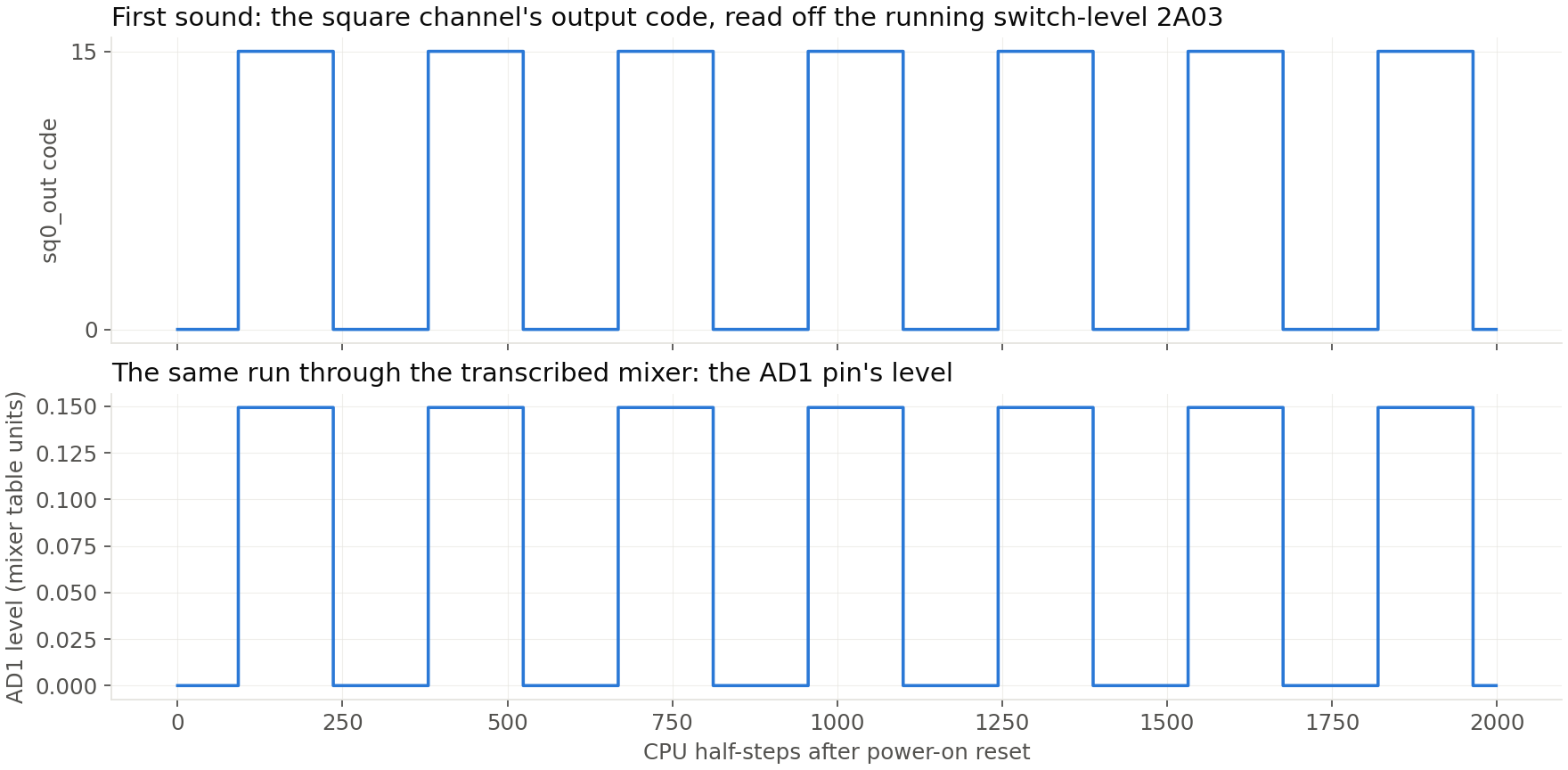
First sound, and the note is exactly the program's
A small program of ours runs on the chip through a memory harness and makes the square channel sing. The reference’s own run of the same program replays through the harness bit for bit over 2,001 states: the core, the audio units and the bus glue under one comparison. And we measured the note itself rather than assuming it: the channel’s output swings in plateaus of exactly 144 half-steps, ten of them counted, and 144 comes straight from the program’s own timer byte (8). As sabotage, the test harness serves that byte wrong, and both checks fail: the replay at the byte’s first bus crossing, and the plateau count at exactly the number the wrong byte predicts.
The PPU's contested corners, pinned by crafted traces
The questions emulator folklore argues about were each answered by a scripted register program on the switch-level PPU (2c02), with the reference simulator running the same script blindly and dumping every node inside the windows that matter. Sprite 0 hits at line 91, dot 182, the sprite’s own x plus the two-dot pipeline, and the two sprite windows replay node for node over 600 states with no exceptions. The famous missed-vblank window measures about a dot and a half wide, and three reads across the flag’s rise return bit 7 as [0, 0, 1] (miss, suppress, consume), cross-checked against the reference’s own sampled data bit. OAM showed no corruption under either documented trigger.
Two engine divergences, both found by the chips and fixed in the engine
Getting sprite 0 to hit at all exposed the first: the OAM data lines the reference special-cases when a group holds both rails, which the engine had been crushing to zero; halfphi 0.1.5 carries the fix as a generic hold with an area-weighted charge vote, the reference’s own rule. The second hid until a palette write was paced the way a real CPU paces it: the byte landed ORed with the address low byte on our engine and as written on the reference, and the cause turned out to be how an undriven group resolves. The 2C02’s reference weighs the members’ areas; visual6502 lets any one charged member win. halfphi 0.1.6 lets a netlist declare which, and with the vote declared the PPU’s two recorded reference runs replay with no exceptions at all: 601 states from power-on and 4008 states through the bus harness, every one of 10,906 nodes. The 9 and then 27 latches those runs had masked as undefined power-on state were the charge rule, not the silicon. A check now holds the declaration, and building the chip under the old rule turns that check red.
The fast PPU matches the chip dot for dot, well inside the frame period
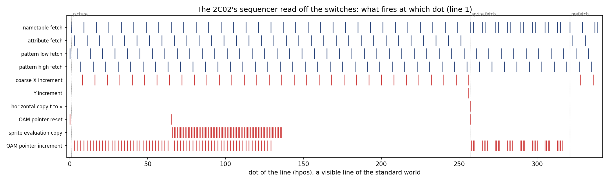
The fast PPU is not a second model of the chip. Its sequencer is a table measured out of the switch-level chip at build time, one event word per dot of a frame: which fetch the chip latched, when it stepped its address, when it copied the scroll, when the flag rose. Only the datapath is authored, and it is held to the chip’s own frames: 62160 visible dots agree with the switch-level render on the first world, all 61440 on a world of 64 sprites (flips, priority, nine on one line, the sprite-0 hit landing at (92, 183) where the chip’s own flag rose at dot 185), and all 61440 on a scrolled world with five register writes landing mid-frame, each inside its bus access (a plateau at dots 1, 2, 3 after the access starts). It renders a frame in 1.092 ms against the 16.639 ms frame period, 15.2 times inside it, worst frame 1.772 ms, over 200 frames.
The 2A03's core at the 6502's pins, chip against chip
The console sketch calls for a new kind of check, chip against chip through the contract, and both halves now exist. The 2A03’s 6502 core is presented as a pin frame of the 6502 project’s own contract crate, one per clock phase, and then run through every trace in the 6502’s recorded pin runs (289 of them: seven programs, the reference’s program, the scripted interrupt and RDY runs, three decimal-mode chains, all 256 opcodes), the other chip entering as recorded text and never as an engine. 285 traces compare (4 drive pins the 2A03 does not have and are refused by name), 131 of them exact in every field at every half-cycle, and the rest differ only inside four named and bounded classes: the stack page (the two dies’ simulated power-on stack pointers differ by $40, derived from both cores’ own registers), the data byte in a write’s phi1 half (nothing is serviced there), the decimal chains, where the 2A03 stores the binary sums and binary flags the 6502 adjusts, 9 bytes listed with their arithmetic, and a mid-run reset, where the 2A03 holds its core still under RES while the 6502 runs on, both reading the vector at the same half-cycle. That list decided the shape of the 2A03’s own fast core: the 6502’s fast core with its decimal adjust disconnected and its stack pointer seeded from this chip, two knobs landed in the 6502 repository and held to its recorded runs there. Against the switch-level 2A03 on every program and script: 285 programs, 65561 half-cycles, the write-phi1 byte the one difference left.
The APU as tables, held to the chip at every half-step
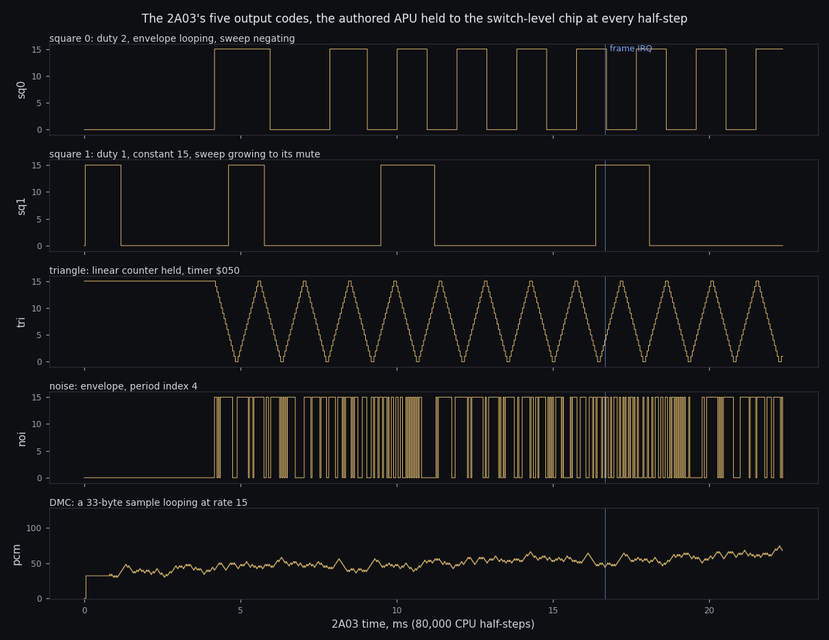
The sound side follows the PPU’s pattern: tables measured out of the switch-level chip at build time, machinery authored around them from headless probes, the whole held to the chip’s own output. The probes came first, eleven measurements kept as instruments (the frame sequencer in both modes, the length table, the duty sequences, the envelope and sweep clocks, the triangle, the noise and DMC period tables, the sprite DMA, the controller strobes), and they found two things the published model does not say. The noise and DMC timers are not counters but linear feedback shift registers, free-running from power-on, each reloading one of sixteen recorded states when it reaches a terminal: the die’s period ROMs, and the noise ROM’s index 12 lands at 964 cycles where every published table says 762, either a transcription defect in the die data or a quirk of the part, named and carried. Every timing inside a unit is a fitted constant measured with a probe the first time the authored stream and the chip’s parted: a low-byte period write makes the next tick a reload, a square’s code lags its step by two half-steps, the DMC’s output unit counts eight completions from power-on before it speaks. The check is two register programs under both frame modes, 10 worlds of 80001 half-steps each, the five output codes and the frame IRQ flag identical to the switch-level chip at every half-step. Then the stalls: the whole chip at the pins, its DMA units taking the bus, against the switch-level chip frame for frame with RDY compared like any other field, a sprite DMA at both write alignments (1201 frames each, RDY low on 1029 and 1027) and the DMC’s sample fetches (4201 frames, RDY low on 19). With everything attached the chip runs at 32,067,032 half-cycles a second, 9.0 times real time. The account, step by step, is the N3 report.
Both chips on one clock, and the standard test ROMs run with a real CPU attached
The glue came first: the NES-001 mainboard’s handful of parts, the address decoder, the PPU’s address latch, the two RAMs, the controller port buffers with the controller behind them, the reset chain, each a few lines held to its datasheet by its own test and labelled authored, since nothing there goes through a netlist. Two of them were authored wrong the first time and the tests said so. Then the console: the 2A03’s fast core and the fast PPU on one master half-step counter, the CPU advancing every twelve and the PPU every eight, at the alignment measured off the two switch-level chips’ own clock dividers (cpu_phase 4, ppu_phase 3, one of 24 the dividers can power up in, and the one the run stamps). The plumbing check runs a test cartridge for 6 frames and holds the master counter to eight per dot, the odd frames a dot short, the picture to the standalone PPU’s, and the NMI count in RAM to one a frame. It runs at 125 to 140 frames a second on one core, 2.1 to 2.3 times real time. The alignment check then holds the seam the whole arc was about, two ways. The PPU’s real NMI is made to land around a BRK at 8 offsets a cycle apart, and the console’s CPU is compared with the switch-level 6502 driven by the same edge, half-cycle for half-cycle: 960 of them agree, the vector taken, the pushes, the timing. And the $2002 read race is measured on the switch-level PPU at every half-step with the console’s own access shape, then the console’s reads are held to that table under all 24 alignments: 145 reads around the flag’s set and 185 around its clear, every half-step of both windows reached, every outcome the chip’s. Then the check the whole arc was built toward, against something real: blargg’s test ROMs through the entire console, the first real programs the fast chips had run for millions of cycles. The CPU timing test passes; 16 of 16 instruction tests pass, every official and unofficial opcode; 11 of 11 sprite-hit tests pass, the double-height one since the fast PPU's tall-sprite rule was measured on the switch-level chip and held dot for dot; 5 of 10 vblank and NMI timing tests pass, the rest one or two dots from the documented console and all one question: its NMI reaches the CPU about two dots later than the two chips, each held to its own measured timing, allow, and a scope on the real board is what settles it; 8 of 8 APU tests pass, six of them only after each miss was measured on the switch-level 2A03 and authored there: the $4017 write’s parity jitter and its immediate clock, a status latched a half-step after the bus is asked, an IRQ flag that stays set for three cycles, and a DMC byte counted off where its read lands. What the ROMs found is the point of running them: the fast CPU had replayed every recorded trace exactly and still carried misses no trace had covered (a carry that rides an undriven bus line into the next instruction, a shift’s carry read from the wrong capture, three opcodes whose result is a bus fight the switch model settles its own way, the half-cycle at which an interrupt input is sampled, which the alignment check caught, and a byte latched later than the bus is asked for it), and the fast PPU four more. Each was located by running the switch-level chip and its fast counterpart in lockstep on the ROM until they disagreed, measured on the chip, then authored and held by a fixture that goes red without it. The account is the N5 report; the play test waits on a cartridge.
The console's frames through the television model, and a capture of them scored
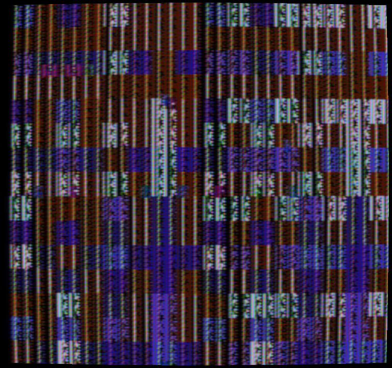
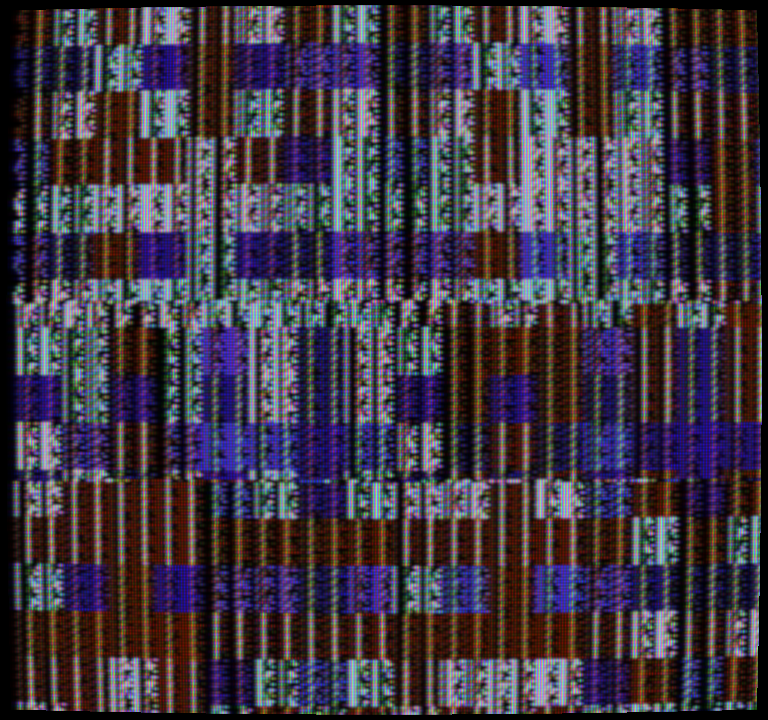
The picture is ntsc-crt’s chain (v0.2.8, pinned by tag) with two things added by the console: the order of the frames and the subcarrier phase carried from one to the next, which the odd frame’s short line moves, so the console hands over its parity and not just its dots. Each frame is encoded by the NES source, decoded on the three-line comb and run through the CRT stages at their authored parameters. Two checks hold it: a console frame through that chain is the standalone fast PPU’s frame from the same world through the same chain on every decoded sample (1474560 components equal, a OddShort frame, 768 by 720 on the screen), and the phase after 12 console frames, 4 of them short, is what the grid’s arithmetic gives that sequence (phase 4; forcing every frame even reads differently and turns the check red). The bars cartridge the real comparison wants paints with the PPU’s rendering off, which the fast PPU had never been asked about: measured on the switch-level chip, the picture with rendering off is the palette entry the address register points at, and its timing against a mid-line write is now a fixture there. Then the capture path, the machine half of the comparison the real console will join: a bars cartridge through the console, its frames through ntsc-crt’s capture-card model and recovered exactly as a real record is, the synthesis through the model’s own front end so both sides carry the same band limit, then every flat region scored against that synthesis through the identical decoder, 5 dots in from its edges, a distance derived from the decoder’s chroma filter rather than chosen. The tolerances were written down before the run: luma within 0.01, hue within 1 degree, saturation within 5 percent. The cartridge is the repository’s own, since blargg’s bars are sixteen dots wide and the decoder settles in five: thirty-two-dot cells of the twelve hues at one luma row and the backdrop, the row stepping every two seconds, scored one run per row. luma row 1: 13 of 13 regions hold all three (worst luma 0.0001, hue 0.3 degrees, saturation 0.0011, rate found to +0.7 ppm); luma row 2: 13 of 13 regions hold all three (worst luma 0.0001, hue 0.3 degrees, saturation 0.0012, rate found to +0.7 ppm); luma row 3: 13 of 13 regions hold all three (worst luma 0.0001, hue 0.3 degrees, saturation 0.0005, rate found to +0.7 ppm); luma row 0: 13 of 13 regions hold all three (worst luma 0.0001, hue 0.3 degrees, saturation 0.0008, rate found to +0.7 ppm). The roundtrip closes. The first runs found the instrument three times before the scoring’s own geometry: a level re-referencing a histogram bin coarse, a dark picture taken for blanking, and the darkest colours’ chroma troughs taken for sync edges, each fixed in ntsc-crt and re-pinned. The real record of the same cartridge on the real console is the bench item, and the cartridge exists for it now; the account is the N6 report.
The console's sound through the board's audio stage, held to blargg's mixer tests and set beside his recordings
The 2A03’s five output codes leave the chip after every CPU half-cycle and go through the two DACs, the nesdev table the family has carried since first sound, authored and labelled so. What happens next is on the NES-001 schematic, read directly: each audio pin pulled down by 100 ohms (the table’s own “plus 100”), the two pins summed through 20K and 12K (the ratio the table’s two constants already carry), a coupling capacitor into a 74HC04 inverter held linear by a 47K feedback resistor with 220 pF across it. So, to the jack: a high-pass with a time constant of 7.50 ms, a gain of -2.350 with the inverter’s sign, a low-pass at 10.34 microseconds, then a windowed-sinc resampler to 48 kHz at the exact rational times. The stage is held to that arithmetic (a step decays by 0.3679 per time constant, a 10 kHz tone against a 200 Hz one comes through at 0.8401 where the values give 0.8433). Not modelled and said so: the inverter’s finite open-loop gain and its rails, and the table’s absolute volts, which is one scale factor a scope record supplies. The check against real hardware is blargg’s: four mixer ROMs, each playing a channel while the DMC plays its inverse, so a right mixer cancels to near silence between two reference beeps. Each ran through the whole console; the worst 100 ms window of each test, as a share of the beep, must stay under 5 percent (the DMC’s step alone is about two), the noise ROM held on its tone since it fades noise by design. Console, then blargg’s recording of the same ROM on real hardware measured by the same code: square 2.4 percent against 6.1; triangle 2.7 percent against 3.0; noise 21.1 percent against 19.0; dmc 3.1 percent against 5.6. Triangle and noise agree with the real console to a fraction of a percent. Square and dmc carry twice the console’s residual on real hardware, and that residual is a tone: the real pulse and DMC DACs depart from the table’s curves by more than the table departs from blargg’s inverse, which is the scope’s question and is recorded, not held. Mixing through the wiki’s linear approximation instead turns the check red, at a third of the beep. The account is the N7 report; the AUDIO_OUT record is the bench item.
The console in a window, its picture on the GPU held to the CPU chain, and a second target in the browser
A frame’s time on one core was measured before anything was written, and it said where the work had to go: the console and the encoder fit a core, and the comb decode with the five CRT stages did not fit anywhere on the CPU. Those two are now eight compute passes on the GPU, every constant uploaded from the decoder and the CRT parameters rather than typed, and they are held to the signal path’s own CPU chain on every component of every pixel of three consecutive frames, the last one black so that persistence shows. With the authored parameters the worst component differs by 4.8e-7 and the mean by 1.2e-8; with the mask and the geometry switched on, 2.8e-5 and 1.9e-7; the tolerance stated first was 1e-3 and 1e-5. A frame takes 0.94 ms on the NVIDIA GeForce RTX 3070, upload included. Skipping persistence turns the check red. The window is a Linux binary: the console with its sound on its own thread, advanced by whole frames per period as the signal path’s drift policy decides from the wall clock, duplicates and drops counted and never resampled in time; the display encodes each new frame and runs the GPU picture; sound through the audio device; the keyboard, and a gamepad through gilrs, as controller 1. The loop is held on a synthetic clock: at exactly the period 60 ticks run 59 new frames with 1 duplicate and 0 drops; at half the period 31 of 60 ticks present the previous frame again; at twice it drops 19 in 20. It ran under a virtual display on this box; a real screen, a speaker and a hand are the desk items. The second target is the browser: the console with its sound behind wasm-bindgen, measured under node on full_palette.nes: 300 frames in 3.56 s, 84.3 frames a second, 1.40 times real time, 798.7 sound samples a frame. That target has a page now: the console runs here, on a cartridge from your own disk, through the same signal path the ntsc bench runs, with the drift counters shown raw. The account is the N8 report.
The bench: the part and the model under one input history
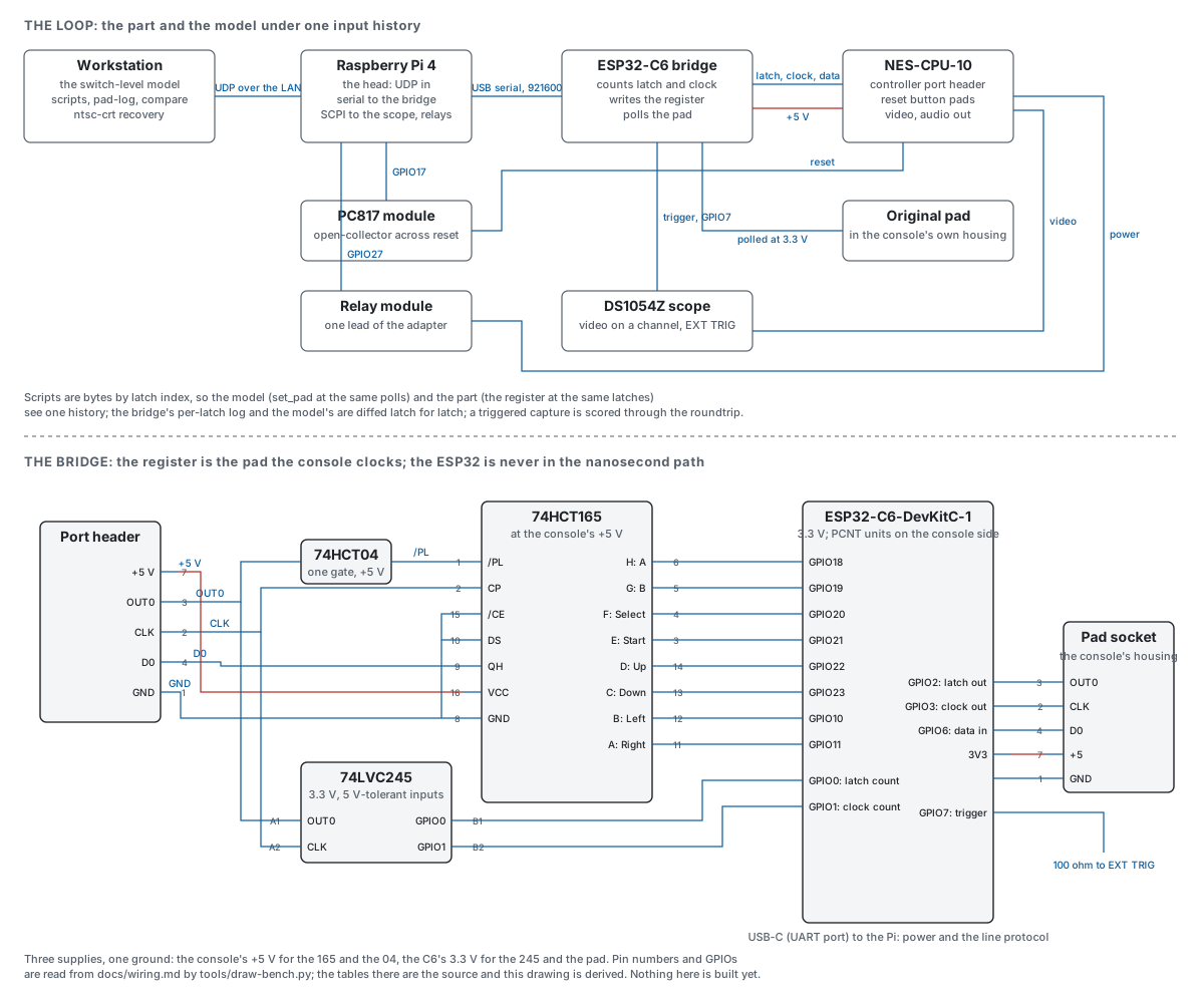
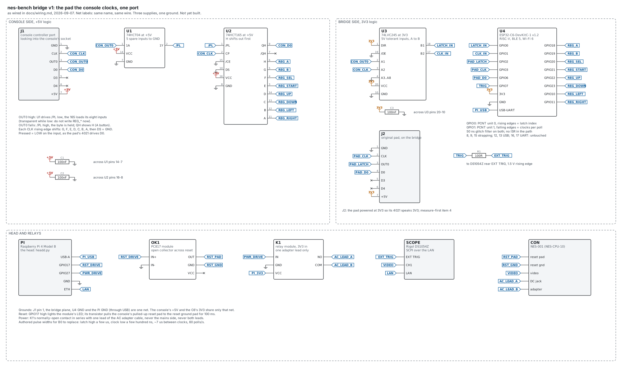
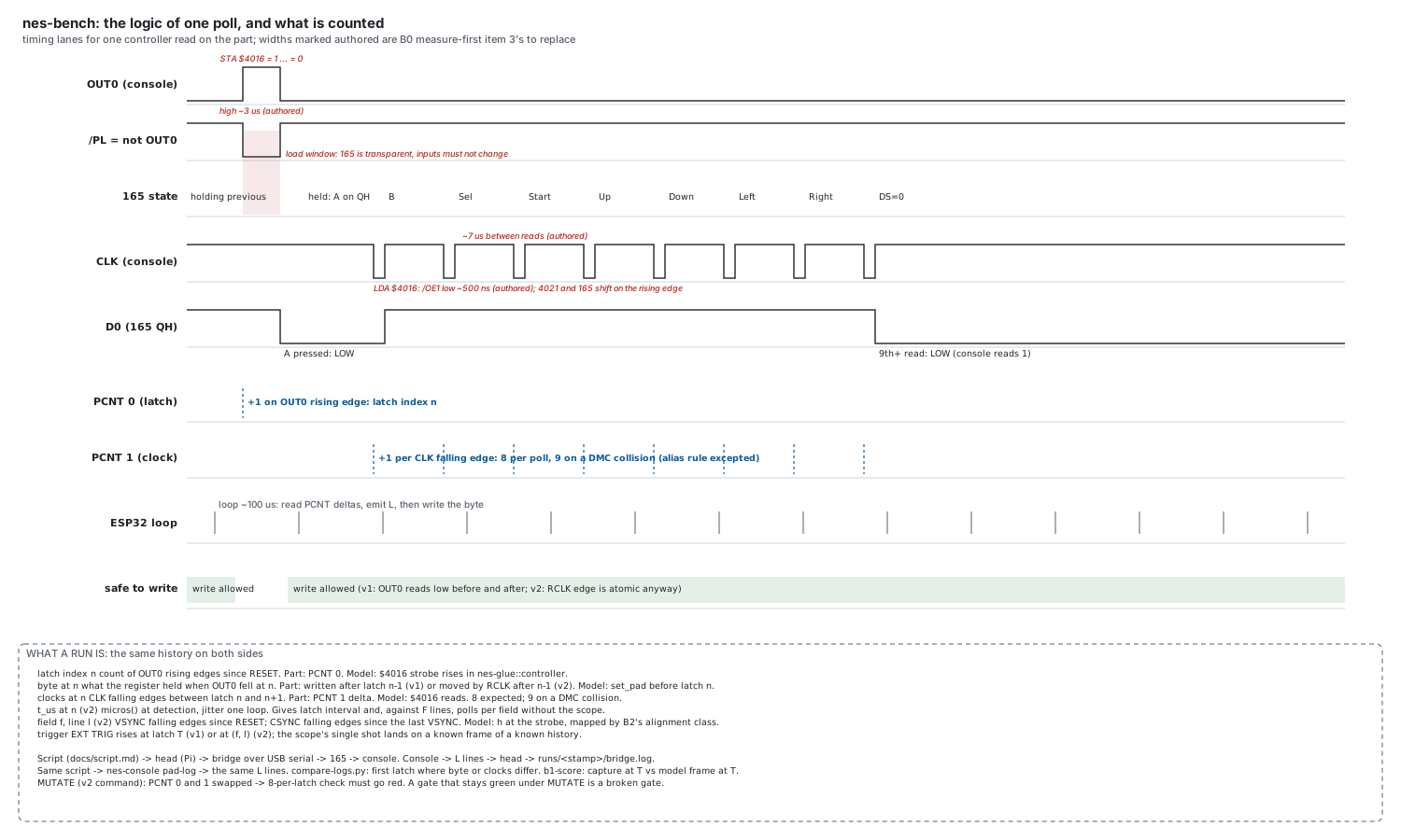
With every machine milestone closed, what the console does not yet know about the part waits on a bench, and the bench is the next thing built. A bridge sits between the console’s controller port and an original pad: a shift register on the bridge is the pad the console clocks, a microcontroller writes its inputs between polls and counts the console’s latch and clock pulses in hardware, and a Raspberry Pi on the LAN takes scripts, drives the reset and power relays and triggers the scope. Scripts are bytes by latch index, so the model and the part see one history; the bridge’s per-latch log and the model’s are diffed latch for latch, and a triggered capture is scored through the same roundtrip the picture milestone closed on. The plan names four milestones with their checks before any firmware, and the first, the sniff, already moved the model: asked what a DMC fetch does to a pad read, the switch-level 2A03 answered before the part could, and the core, the fast chip and the console changed for it, each change held by a sabotage test that goes red without it. Every milestone’s tool now exists ahead of its hardware, from the head that plays a script onto the bridge, the relays and the scope, to the bisection that finds the first poll at which the part and the model disagree, each proved against a stand-in by a sabotage test that goes red without it. The drawing below is derived from the wiring tables by a script, so it cannot disagree with them. Plan, wiring, the script and the running report are in the notebook; the repository is github.com/tinymachines/nes-bench.
Every number here comes from re-running the tests
The figures below come from running both chip repositories’ own suites again on 2026-09-07, with their netlists and every recorded reference run required, plus their MUTATE=1 runs, all at the recorded commits; this page reads only what those runs wrote.
What the sketch asked for, and what still waits on the part
The plan was written down first: the end-to-end sketch in the contract repository, with a check per milestone. Every milestone it names is built and checked on this machine: the contract, the two chips at the switch level and the fast chips built from them, the fast 2A03 assembled whole, the glue, the console on one clock running the standard suites, the picture through the encoder and back through the capture path, the sound through the board’s own stage, and the shell with its GPU picture, its gamepad and its browser target. What is left is exactly what a switch-level model cannot settle alone, and each item is named in the reports: the NMI’s arrival timing on a real board, a real cartridge in the play test, the terminated capture the picture milestone asked for, the sound stage under a real speaker, the alignment the console powers on in, and the die’s own findings, where the model and the part are known to disagree and a logic analyser decides. The bench above is how those close. The signal side is already real: the ntsc page carries frames decoded from a physical console, and its composite deep-dive reads that console’s video off the scope level by level.
The repositories are public: github.com/tinymachines/2a03 and its siblings. The chip crates embed die data derived from visual6502-family imagery, so NonCommercial and ShareAlike travel with them; the contract crate is MIT and embeds nothing.